





Adirondack Chair
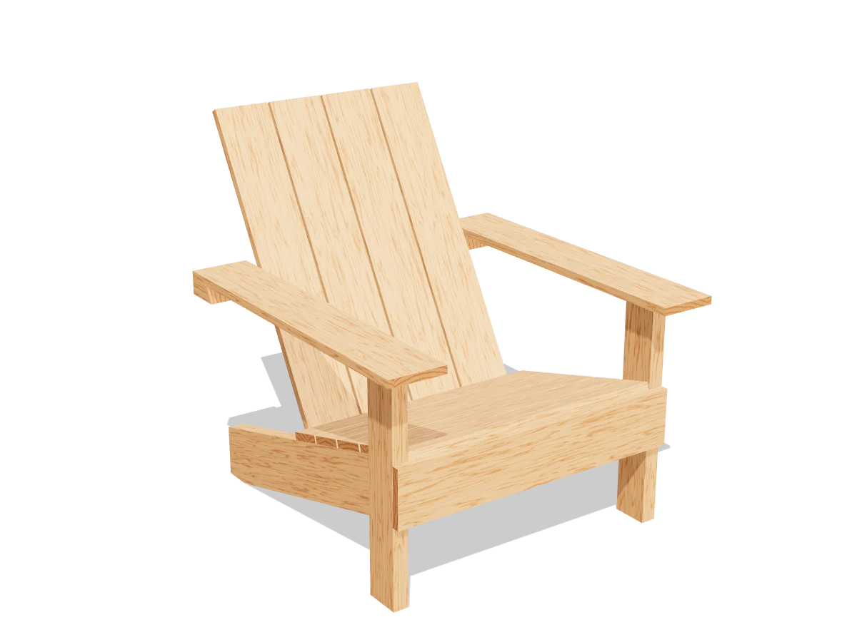
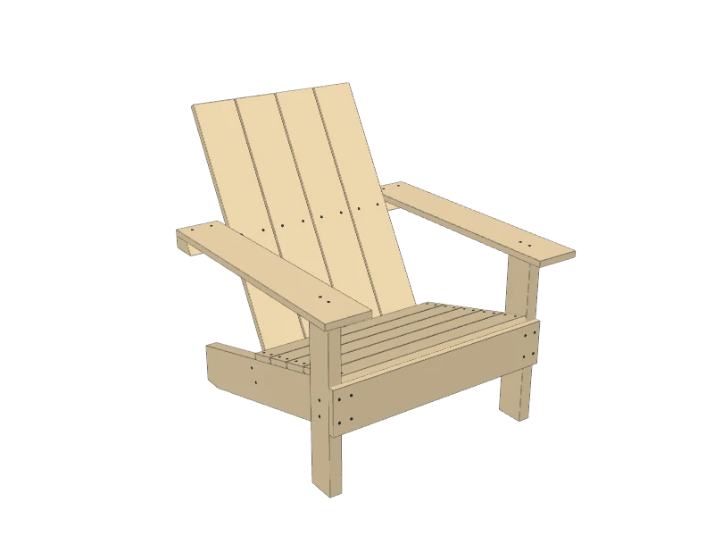
The classic slatted lawn chair: a seat that slopes back 15°, a back that leans 30° and wide arms for a drink. The seat front sits about 14″ off the ground.
- Skill
- Level 4 of 5 · Intermediate
- Build time
- 6 to 8 hours, plus finish
- Lumber
- 1 2x6, 2 2x4s, 3 1x6s and 2 1x4s
- Joinery
- Carriage bolts and deck screws
- Finished size
- about 33¾″ W × 37⅝″ D × 35¾″ H
A 2x6 is actually 1½″ × 5½″, a 2x4 is 1½″ × 3½″, a 1x6 is ¾″ × 5½″ and a 1x4 is ¾″ × 3½″. Every measurement in this plan uses the real size.
Shopping list
- 12x6, 8 ftCedar or pressure-treated. The stringers.
- 22x4, 8 ftCedar or pressure-treated. Legs and back supports.
- 21x6, 6 ftCedar. Back, apron and arms.
- 11x6, 8 ftCedar. Back, apron and arms.
- 11x4, 8 ftCedar. The seat slats.
- 11x4, 6 ftCedar. The seat slats.
- 4⅜″ × 3½″ galvanized carriage boltsWith washers and nuts.
- ~102″ exterior deck screws
- ~501⅝″ exterior deck screws
- ~102½″ exterior deck screws
- 63″ exterior deck screws
- 1Exterior wood glue
- opt.Exterior oil or stain
Tools
- Miter sawFor the 15° stringer cuts.
- Circular saw or table sawThat tilts to 30°, for the arm support bevel.
- Drill/driverWith a ⅜″ bit for the bolts.
- Wrench or socket
- Clamps
- Speed square, tape measure, pencil
Cut list
| Part | Qty | Size, inches | From |
|---|---|---|---|
| AStringersEnds cut at 15°, parallel, with a level foot at the back. | 2 | 1½ × 5½ × 33⅝ | 2x6 |
| BFront legs | 2 | 1½ × 3½ × 21½ | 2x4 |
| CApron | 1 | ¾ × 5½ × 29 | 1x6 |
| DLower back support | 1 | 1½ × 3½ × 23 | 2x4 |
| EArm supportOne long edge beveled at 30°. | 1 | 1½ × 3½ × 33¾ | 2x4 |
| FSeat slats | 5 | ¾ × 3½ × 26 | 1x4 |
| GBack slats | 4 | ¾ × 5½ × 35 | 1x6 |
| HArms | 2 | ¾ × 5½ × 32¼ | 1x6 |
Board layout. Each row is one board, cut left to right, with the remainder hatched. Dark lines are saw cuts, about ⅛″ wide.
Build it
 01
Cut the pieces
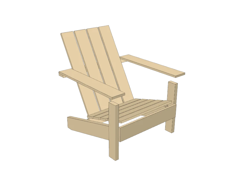
Cut the square pieces to length. Cut the stringers (A) and the arm support (E) to the blank lengths below for now: the next step shapes them.
- A Stringers, two at 33⅝″
- B Front legs, two at 21½″
- C Apron, one at 29″
- D Lower back support, one at 23″
- E Arm support, one at 33¾″
- F Seat slats, five at 26″
- G Back slats, four at 35″
- H Arms, two at 32¼″
 02
Shape the stringers and the arm support
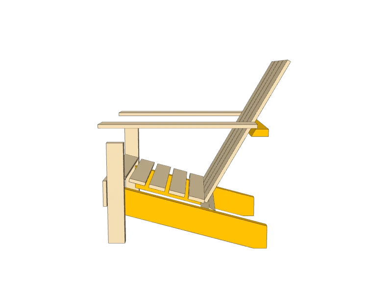
Set the miter saw to 15°. Cut the front end of each stringer (A) at that angle. Measure 32¼″ along the top edge and cut the back end parallel to the front, so both ends stand plumb when the top edge slopes 15°.
Now the foot: from the bottom corner of the back end, measure ¾″ up the back end. Draw a line square to the back end from that mark to the bottom edge and cut on it. That flat sits on the ground.
Tilt the circular saw or table saw blade to 30° and bevel one long edge of the arm support (E), so its top face is about ⅞″ narrower than its bottom face. The back slats lie flat on this bevel.
TipCut one stringer, check it against the drawing, then trace it onto the second board so the two match.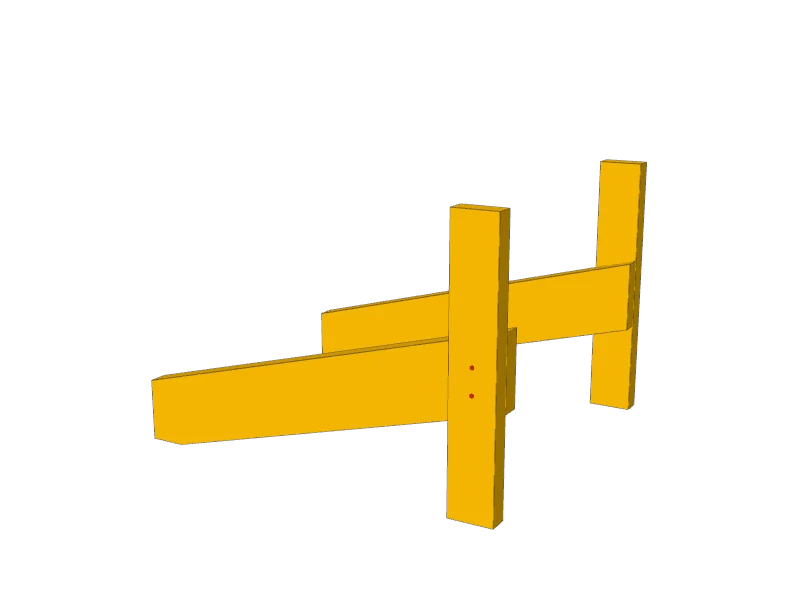 03
Bolt the legs to the stringers
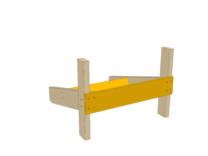
Stand a front leg (B) on the floor and clamp a stringer (A) to its inside face, the stringer's front end flush with the front of the leg and its foot flat on the floor. The top of the stringer's front end should be 13¼″ up from the floor.
Drill two ⅜″ holes through the leg and the stringer and fit ⅜″ × 3½″ carriage bolts with washers and nuts. Build the other side as a mirror image.
 04
Add the apron and lower back support
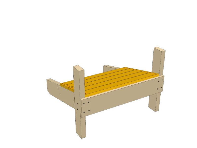
Stand the two sides up 26″ apart at the outside. Screw the apron (C) across the front of the legs and stringers with 2″ deck screws, its top flush with the tops of the stringers.
Fit the lower back support (D) between the stringers near the back, tilted back 30° from plumb, its lowest edge about 4¼″ above the floor. Drive two 3″ deck screws through each stringer into its ends.
 05
Screw down the seat slats
Lay the first seat slat (F) on the stringers right behind the apron, flush with the outside of the stringers. Space the rest ¼″ apart. Drive two 1⅝″ deck screws through each slat end into the stringer.
 06
Add the back slats and arm support
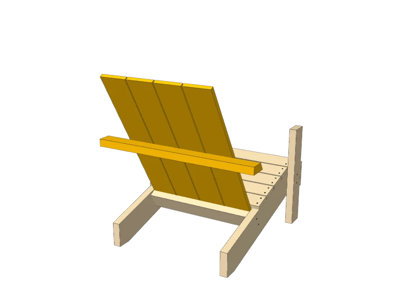
Stand the four back slats (G) against the back of the lower back support (D)'s front face, their bottoms flush with its bottom edge, ¼″ apart and centered. Two 1⅝″ deck screws through each slat into the support.
With a helper holding the back at 30° from plumb, set the arm support (E) behind the slats, bevel against them, its top 21½″ above the floor and level. Screw through each slat into it.
TipA speed square has a 30° mark. Hold it against a slat and a level to check the lean.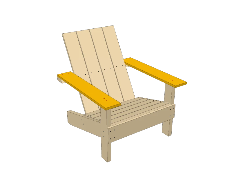 07
Add the arms
Lay each arm (H) on top of its front leg and the arm support, its inside edge against the outside back slat and its back end flush with the back of the arm support. Glue and drive two 2½″ deck screws down into the leg and two into the arm support.
 08
Finish
Round over the front edge of the seat, the arm ends and every corner people touch, and sand smooth. Leave cedar to weather gray, or brush on an exterior oil or stain.
Watch outCheck the bolts and screws each spring and tighten them. Set the chair on level ground so both legs and both feet bear.
Build at your own risk. Check every measurement against your own lumber before you cut, test-fit before you glue, and wear eye and ear protection.